Safety Warning
Power AdapterInput: AC 100V ~ 240V, 50/60Hz; @0.8A
Output: DC 5V, 1A , USB Type-C
Use the power adaptor in strict accordance with the specifications, or it may cause damage to the device.
BatteryThe internal part of the instrument is a lithium battery. In order to give full play to the performance of the battery, when using the instrument for the time, please use the internal battery to supply power. After the battery runs out , charge the battery then.
The first charging time should be not less than 5 hours. The charging temperature range of the battery in the instrument is -10℃ ~ 50℃ . When temperature is too high, please stop charging for safety.
When the instrument is idle for more than 3 months, it should be charged in time to maintain the battery power. The temperature range of battery for long-term storage is -20℃~45℃.
Do not take out the battery without permission. Please keep the battery away from the fire source and strong heat; Do not open or damage the battery.
Laser Safety Instruction
The laser safety level of this instrument:
OTDR: CLASS II;
Visual Fault Locatyor: Class III B,
which is harmful to human body.
When using this instrument, please avoid looking directly at the laser output port, and do not look directly at the end of the optical fiber when testing; When the instrument is used , please cover the dust cap of the light output port. When the visual laser source function of the instrument is turned on, please do not look directly at the output port of the visual laser source or the tail end of the optical fiber connected to the visual laser source output port , so as to avoid eye injury.
Known Before a Test
Live Test (In-service Test)
TN1700-D22 (1310nm &1550nm) Does Not support live test
TN1700-P1 (1550nm) Support 1310/1490/1577/1610/1625nm live fiber
TN1700-P2 (1610nm) Support 1310/1490/1550/1577nm live fiber
TN1700-A22 (1625nm) Support 1310/1490/1550/1577nm live fiber
* Online Power Value over 0dBm is not permitted
Laser Type
1310/1550nm: FP-LD
1610nm: DFB-LD
1625nm:DFB-LD
1650nm: DFB-LD (optional)
* VFL: 650nm Red Light and 515nm Green Light are optional
Test Result Storage
The TN1700 OTDR comes with built-in memory and can also be expanded with an external SD card. It supports a maximum external expansion of 32G SD card. It is NOT recommended to store too much data on the SD card as it may affect the smoothness of device operation.
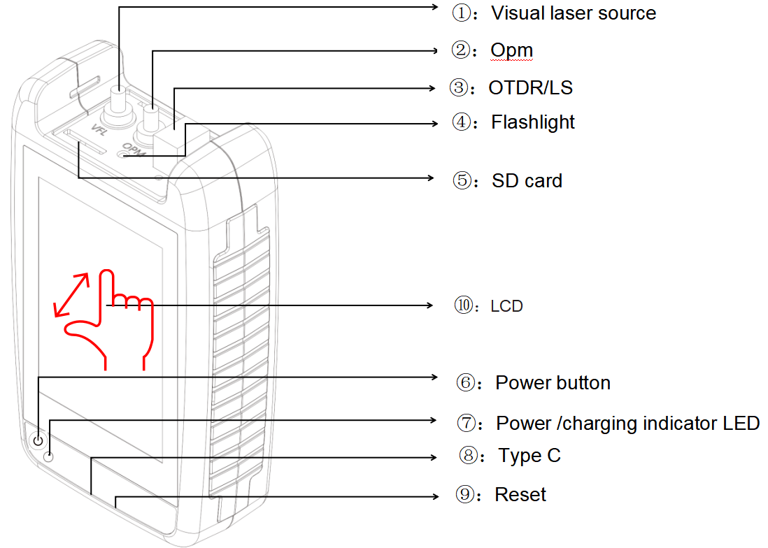
Component Description
| Number |
Function |
Description |
| 1 |
VFL
|
Visual Fault Locator Port
|
| 2 |
OPM
|
Optical Power Meter Port
|
| 3 |
OTDR/ LS
|
OTDR/Laser Source port
|
| 4 |
Flashlight
|
Short press the power button to operate
|
| 5 |
SD card
|
Supports up to 32GB SD card expansion
|
| 6 |
Power button
|
POWER ON/OFF
-Long press:power on/off
-Short press:Turn on/off flashlight
|
| 7 |
LED
|
-Red indicator charging, fully charged and turned off.
-Flashing indicator: No battery installed
|
| 8 |
USB Type C
|
Used for charging and transmitting data
|
| 9 |
Reset key
|
Used to reset the instrument panel when a system crash occurs
|
| 10 |
LCD
|
resolution:320X480 TFT Capacitive LCD screen, supporting multi touch control.
|
Operating the TN1700
Turn on the instrument
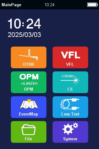
Press【POWER】button to turn on the TN1700. Aftern entering the main interface, you can see the various functional modules of the TN1700.
Turning on and off the flashlight
In the power on state, short press the 【 POWER 】 button to control the flashlight on and off
Shutdown
Long press the POWER button to shut down.
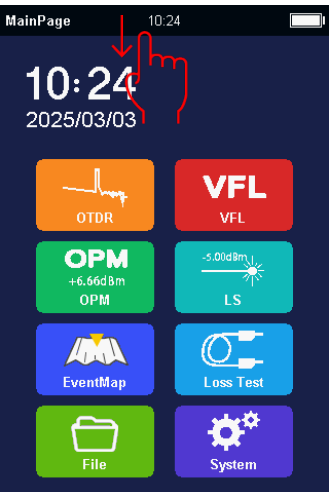
Shortcut menu
In any interface, there is a shortcut menu at the top of the screen. Scroll down to pop up: [Screenshot], [Flashlight], [Shutdown], [Return]
Main interface module: seven functional modules
1) OTDR
2) OPM
3) VFL
4) Event map
5) Laser source
6) Loss tester
7) Flashlight(Controlled by short pressing the power button or using a drop down menu)
* Swipe the screen from top to bottom to call out down menu, including screen shot, Flash Light
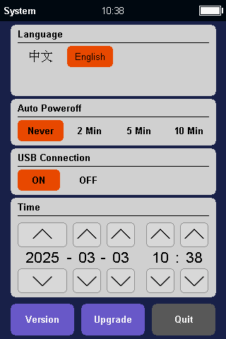
System setting
Language: English/French/Spanish/Portuguese/Italian/German/Korean/Russian
Auto off: Long term inactivity can achieve automatic shutdown, and the waiting time can be set according to one's own needs.
USB data export:
When connected to a computer, turn on USB Data Export and the device will automatically drive as a USB drive on the computer. At this point, it can be operated as a USB flash drive on a computer.
Date and Time:
After removing the instrument battery, the system time will be reset.
After reinstalling the battery, the date and time need to be set.
Upgrade:
1)Insert the upgrade package into the instrument panel via USB cable.
2)After unplugging the USB cable, click on 'Upgrade' and the instrument
3)The TN1700 will automatically enter upgrade mode to complete the firmware
update.
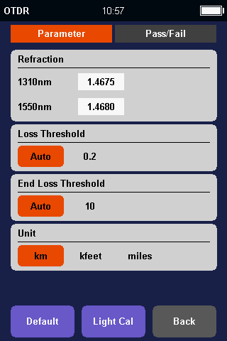
OTDR Parameter settings
wavelength: 1310/1550nm(Configured by the instrument)
Test mode: Manual/Auto
Range: 100m/500m/1km/2km/5km/10km/20km/40km/60km/80km
Pulse width: 5ns/10ns/20ns/50ns/100ns/200ns/500ns/1us/2us/5us/10us
Time:5s/10s/30s/60s/real time
Refractive index:The refractive index of the measured optical fiber, and the accuracy of the refractive index is related to the precision of the instrument measurement.
End threshold: used to determine the end threshold. When the loss at a certain location exceeds the set end threshold, it will be positioned as the end of the fiber cable.
Loss threshold: threshold used to limit loss events. When the loss is less than the set value, the event is ignored.
Auto:The instrument will automatically select the measurement range and pulse width based on the length and loss of the measured optical fiber.
Manual :The instrument adopts the measurement range and pulse width set by the user themselves.
Fiber preparation
The TN1700 OTDR works on any single mode fibers. The single mode fiber means it is with 9um core. And because of OTDR testing theory, please be sure the fiber is not very short, at least 3 meters, and not greater than 80km.
Fiber Connector
There are two kinds of fiber connector, one is APC with 8° angle , the other is UPC (PC) flat end-face .Users are not allowed to change between them. The OTDR port is installed with SC connector in factory default.
Connector Cleaning
Please use connector cleaner to clean OTDR port and fiber connector. Please take off entire dusty cap on the tip of cleaner when you clean OTDR port.When you clean fiber connector, just take off top half dusty cap on cleaner tip.
Start a Test
Start OTDR Testing
After the cleaning work done, you can plug fiber connector into OTDR.
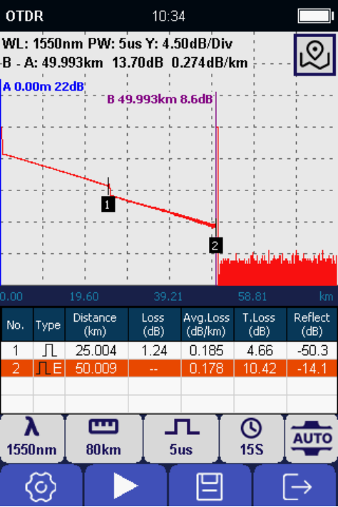
| Curve Part |
|
WL
|
Wavelength
|
|
PW
|
Pulse width
|
|
Y
|
Vertical axis scale in dB
|
|
A
|
The position of cursor A in distance, and
loss at current position
|
|
B
|
The position of cursor B in distance, and
loss at current position
|
| A-B |
Distance between A and B
Loss value between A and B
|
| Event List Part |
|
No
|
Event number from near end to far end
|
|
Type
|
Attenuation event or reflect event
|
|
Distance
|
The distance from first event to current event . Km in unit
|
|
Loss
|
The loss value at current event dB in unit
|
|
Avg.Loss
|
The average loss/km from first event to current event
|
|
T.Loss
|
The total loss from first event to current event dB in unit
|
|
Reflect
|
The reflect signal value dB in unit
|
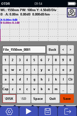
To save OTDR Testing Results
After testing done,press [Save] button to save otdr testing results.
| Name |
Description |
| Cap |
Change upper and lower letter |
| Clr |
Clear what already input |
| Back |
Delete one letter from right side to left side |
| < |
Move cursor from right to left and then insert a letter |
| > |
Move cursor from left to right and then insert a letter |
| Quit |
Back to OTDR testing and do not save current curve |
| \OTDR |
Save to TN1700 |
| \SD |
Save to SD card |
File renaming: Enter the file management interface, then select the file that needs to be renamed, and press[renaming],You can rename the saved file.
Delete file: Enter the file management interface, select the file to be deleted, and click the [Delete] button to delete the saved file.
Event Map
| Name |
Description |
| No |
Event number from near end to far end |
| Type |
Attenuation event or reflect event |
| Distance |
The distance from first event to current event.Km in unit |
| Loss |
The loss value at current event, dB in unit |
| Avg.Loss |
The average loss/km from first event to current event |
| T.Loss |
The total loss from first event to current event dB in unit |
| Reflect |
The reflect signal value dB in unit |
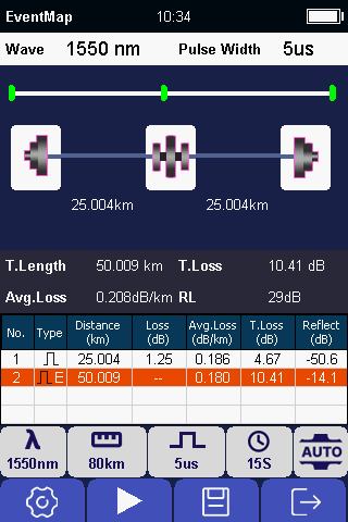
* If you want to view the OTDR curve, you can press the [OTDR] button to enter the OTDR curve display.
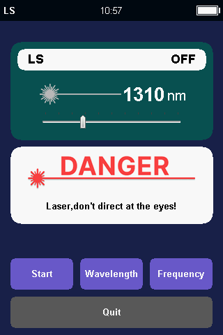
Light Source (OLS) Module
The wavelength of the stable light source is the same as that of the OTDR, and they share the same laser.
Turn on Light Source
Press [Start] to turn on the light source.Once turned on,laser icon at middle of screen will be changed in red.Once laser source is turned off,the color will be back in gray.
Change Wavelength
Press [Wave Switch] button to change wavelength.Wavelength is according to model of the OTDR.
Change Frequency
Press [Freq Switch] button to change frequency,The optional frequency is CW, 270Hz, 330Hz, 1kHz, 2kHz.
Quit:
Press [Quit] button to come back main page.
Warning:
Do not look at light source port.
Laser is not visible , but it is dangerous for human.
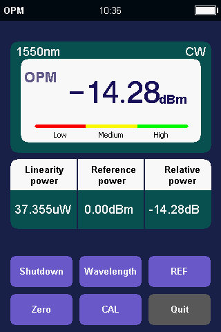
Optical Power Meter (OPM) Module
Turn on optical power meter
Press [Start] to turn on the optical power meter.
Change Wavelength
Press [Wave Switch] button to change wavelength . The optional wavelength is 850nm, 1300nm, 1310nm, 1490nm, 1550nm, 1625nm and 1650nm.
Set REF
Press [REF] button to set current optical power value to a reference.
Set Zero
Press [Zero] button to set current optical power value to zero.
Quit
Press [Quit] button to come back main page.
Calibration: Users can calibrate the power meter themselves.
1. Select the wavelength that needs to be calibrated (Switch through the 'Wavelength' menu)
2. Switch the cursor focus to the set input position of the power meter, adjust the standard power value by pressing the up and down keys, confirm with the [OK] key after adjustment, and then exit to complete the self calibration of the power meter.
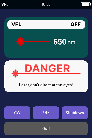
Visual Light Source (VFL) Module
VFL Module
The Visual Fault Locator supports 2 modes.One is CW, the other is 2Hz Flash.
Press [CW] button to select CW. Press [2Hz] button to select 2Hz menu.
Turn off Visual Fault Locator
Press [Shutdown] to turn off the visual fault locator. Once turned off, laser icon at middle of screen will be changed in gray. Once laser source is turned on, the color will be back in red.
Quit
Press [Quick] button to select Quit menu and press [OK] button to come back main page.
Warning:
Do not look at light source port.
Laser is not visible,but it is dangerous for human.
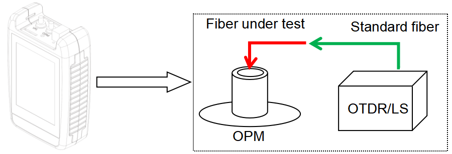
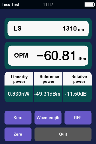
Loss Testing Module
The loss testing module simultaneously turns on the light source and the optical power meter module, using the light source as the transmitter and the optical power meter module as the receiver, to complete the entire loss calculation of the fiber optic link.
- First, connect the light source and the optical power meter using standard optical fibers.
- Then open the 'Loss Test' module.
- Switch the desired wavelength using the 'Wavelength' button.
- After the light source stabilizes (it is recommended to wait for 5 minutes), press [Reference], and the relative power will be displayed as 0dB. The "Reference Value" will be displayed as the current output power value of the light source.
- Pull out the standard fiber and connect the tested fiber in series to the interface of the standard fiber and the optical power meter.
- The current 'relative power' display shows the insertion loss value of the tested fiber.
Download PC software (OTDRtraceView)
Download PDF version
Check Technical Specifications


