Please note that the complimentary upper computer software provided by FirstFiber Technologies is intended for development reference only. Its use is entirely optional. FirstFiber Technologies encourages users to develop their own proprietary control software.
Depending on your network environment, the IP configuration can be categorized into the following three scenarios:
Scenario 1: Direct Connection to a PC (Point-to-Point)
Scenario 2: Within a Local Area Network (LAN)
Scenario 3: Across a Wide Area Network (WAN) / Remote Connection
Before You Begin
Before commencing the configuration, please note the default network settings of the OTDR,
| Parameter |
Default Value |
| IP Address |
192.168.111.249 |
| Subnet Mask |
255.255.255.0 |
| Default Gateway |
192.168.111.1 |
| Port |
5000 |
Scenario 1: Direct Connection to a PC
This is the most straightforward configuration method. Follow the steps below to establish a point-to-point connection.
-
Power on the device.
Connect the OTDR module to a power source using the provided power cable. The OTDR will boot up automatically.
-
Connect the network cable.
Link the OTDR to your PC's Ethernet port using a standard network cable.
-
Verify the connection.
Once successfully connected, the green LED indicator on the OTDR's RJ45 port will begin to flash.
-
Configure the PC's static IP.
Access your PC's wired network adapter settings and assign a static IP address within the same subnet as the OTDR. For example.
-
- IP Address: 192.168.111.2 (or any available address from .2 to .248)
- Subnet Mask: 255.255.255.0
- Default Gateway: 192.168.111.1
Tip: Avoid using 192.168.111.249 for the PC, as this is reserved for the OTDR and will cause an IP conflict.
-
Launch the software.
Open the upper computer software provided by FirstFiber Technologies on your computer.
-
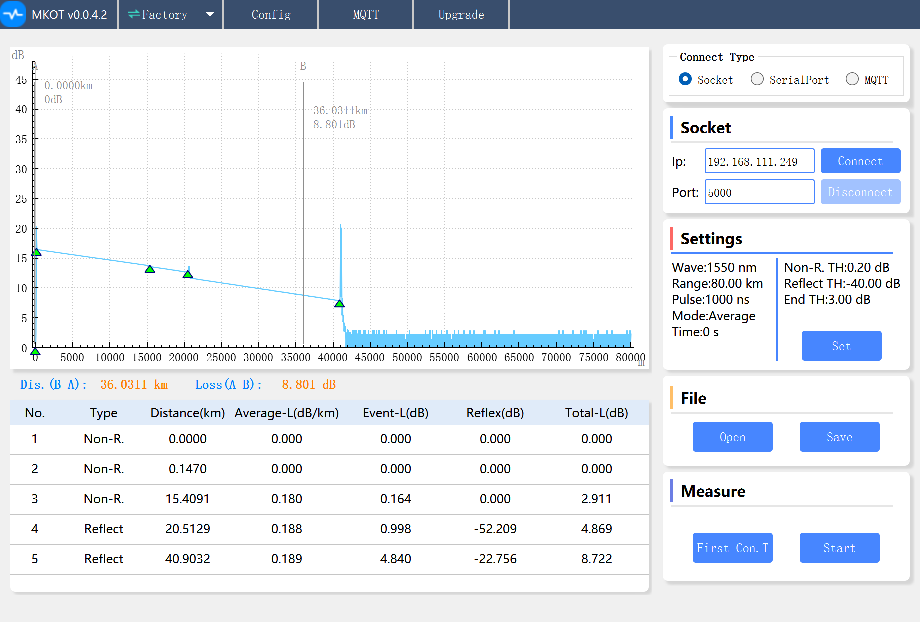
Verify Socket settings.
Locate the Socket section within the user interface. Check that the default IP address and port number match the default values specified in the Before You Begin section.
-
Establish connection. If the settings are correct, click the Connect button.
-
Confirm status. The software will display a confirmation message indicating that the connection has been successfully established (Connection Successful).
Once the connection is successfully established, you can now control and operate the OTDR module via the PC software.
The software interface provides the following primary configuration areas.
- Settings Section. This area allows you to configure essential OTDR testing parameters, including Pulse Width, Dynamic Range, and Wavelength.
- Configure Section. This area is used to set up automated testing workflows, such as Loop Testing (continuous testing) and Test Intervals.
Scenario 2: Within a Local Area Network (LAN)
This is the most common deployment method chosen by the majority of users due to its ease of setup and operational convenience.
The Challenge: Subnet Mismatch
To illustrate how to configure the system, let us assume your PC's current LAN settings are as follows:
- PC IP Address: 192.168.222.249
- Subnet Mask: 255.255.255.0
- Default Gateway: 192.168.222.1
As shown above, the OTDR's factory default IP address (192.168.111.249) resides on a different network segment (subnet) than your PC. To enable network communication, you must modify the OTDR's IP address to match your local network's subnet, rather than changing your PC or local network settings.
Caution
Do not alter your existing local network segment or router gateway settings to match the OTDR's default configuration. Doing so will disrupt your existing network topology and may cause a complete loss of internet connectivity for your PC and other local devices.
To modify the OTDR's IP address to match your local network, follow the steps below,
-
Connect temporarily via Scenario 1.
Establish a temporary direct connection between your PC and the OTDR by following the steps outlined in Scenario 1 to access the software.
-
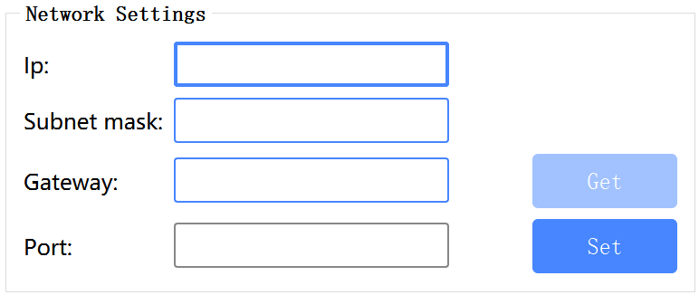
Navigate to Network Settings.
In the host PC software, navigate to Configure > User Settings > Network Settings.
-
Enter the new network parameters.
In the respective input fields, enter the following configuration.
-
- IP Address: 192.168.222.249 (or any available, non-conflicting IP address on your local network, such as .247, .246, or .245)
- Subnet Mask: 255.255.255.0
- Gateway: 192.168.222.1
- Port: 5000
-
Apply the changes.
Verify that all entered data is correct, then click the Set button to write the new network configuration into the OTDR module.
Expected Behavior
Once you click Set, the OTDR will immediately disconnect from the current software session. This is completely normal, as the device is instantly applying its new network settings and leaving the old subnet.
-
Deploy the OTDR to the LAN.
Disconnect the OTDR from your PC. Connect the OTDR module to a power source, and then link it to an available LAN port on your local network switch or router using a network cable.
-
Update software connection settings.
Launch the host PC software on your computer. In the Socket section, update the target IP address to the new static IP you assigned to the OTDR in Step 3.
-
Establish connection.
Click the Connect button.
Once connected, the software will gain control over the OTDR module across the local network, allowing you to perform tests and adjust settings remotely as described in Scenario 1.
Scenario 3: Across a Wide Area Network (WAN) / Remote Connection
Once you are familiar with the first two setup methods, configuring the system for a Wide Area Network (WAN) is relatively straightforward. However, this scenario requires a static (fixed) public IP address.
Before proceeding, you must ensure your network meets this requirement. Standard Dynamic Public IPs (which change periodically) and Carrier-Grade NAT (CGNAT) IPs (often referred to as large private networks or double NAT) will not work.
How to Verify Your Public IP Type
Follow these simple steps to confirm whether you have a true, static public IP address.
- Check for a Static IP: Log into your router's management interface and note the WAN IP address. Reboot the router. If the WAN IP address changes after the reboot, you have a Dynamic IP, which is unsuitable for this configuration.
- Check for CGNAT (Private Network Check): Copy the WAN IP address displayed in your router's interface. Then, open a browser and search "What is my IP" on a public search engine (e.g., Google).
If the two IP addresses match - You have a true public IP address.
If the two IP addresses do not match - Your connection is behind a CGNAT (Carrier-Grade NAT), meaning you do not have a direct public IP.
Step 1: Configure Port Forwarding on Your Router
Once you have confirmed that you have a static public IP address, you must configure port forwarding (sometimes under NAT settings) on your gateway router to route external traffic to the OTDR.
- Access the Router. Log into your router’s management interface via your local network.
- Locate the Port Forwarding Menu. Navigate to the NAT, Port Forwarding, or Virtual Server settings section.
- Create a Port Forwarding Rule. Set up a new rule to map an external port to the internal IP address and port of the OTDR module. Configure the following parameters,
-
- Internal (LAN) IP: Enter the local static IP address assigned to the OTDR (e.g., 192.168.222.249 from Scenario 2).
- Internal Port. 5000 (the default OTDR communication port).
- External (WAN) Port: Choose an available external port (e.g., 5000 or any custom port above 1024).
- Protocol. Select TCP (or TCP/UDP).
Note: Interface layouts and terminology may vary slightly depending on the router manufacturer (e.g., Cisco, TP-Link, DrayTek), but the underlying configuration logic remains identical.
Step 2 Connect Remotely via the PC Software
With port forwarding successfully configured, you can now connect to and control the OTDR from any computer connected to the internet.
- Launch the software on your external (remote) PC.
- In the Socket section, enter your Static Public IP address in the IP field.
- Enter the External Port number you specified in your router's port forwarding rule.
- Click the Connect button.
The upper computer software is now connected via the WAN. You can operate, configure, and monitor the OTDR module remotely from anywhere in the world.


