PREFACE
Thank you very much for purchasing and using this series of optical time domain reflectometers.
This manual mainly contains the common operation and maintenance information of the instru
ment, as well as the common troubleshooting guide and other information. In order to facilitate
your use, please read the contents of this manual carefully before operating the instrument, and
follow the instructions of this manual correctly.
This manual is only used with this instrument. Any company or person is allowed to tamper, copy
and disseminate the contents of this manual for commercial purposes without the authorization of
the company.
The contents of this manual are subject to change without notice. If you have any questions,
please call the supplier, we will provide you with the best service!
Due to the need of design improvement, the contents are subject to change without notice.
Summary
This series of OTDR is a multi-functional optical measuring instrument, which OTDR, event map, visual fault location,
RJ45 Test(cable line length 、sequence test、cable tracking),optical multimeter(Laser Source、optical loss test),optical power
meter, end face detection,and other functions. It has touch screen and heys. It is the right assistant for optical cable construc
tion, installation and maintenance, project acceptance and on-site repair
Warning
When using the instrument, do not look directly at the laser output port or the end of the optical fiber with your eyes, avoid
eye damage!Dual wavelength testing of 1310nm&1550nm is prohibited online, as forced use may cause damage to internal
components of the instrument!Any change or modification not explicitly permitted in this manual will deprive you of the right
to operate the equipment. To reduce the risk of fire or electric shock, do not expose the equipment to thunderstorm or humid
environment. In order to prevent electric shock, please do not open the shell. It must be repaired by qualified personnel
designated by the manufacturer.
Attentions
Battery: The battery is a special polymer lithium battery, the charging voltage is 5V/2A, and the charging temperature
range is -5℃~+45℃. When the ambient temperature is too high, the charging will automatically terminate. The battery should
be charged every one month to avoid long storage time and failure of battery due to self discharge. The temperature range of
battery during long-term storage is: - 20 ℃ ~ 50 ℃.
Please use the special adapter attached with the instrument box and use the external power supply in strict accordance
with the specifications, otherwise the equipment may be damaged.
End Face Cleaning: Before testing, clean the end face of the tested fiber joint with alcohol cotton.
LCD screen: The display of this series of instruments is 4.3 inch color LCD. In order to maintain good viewing effect, please
keep the LCD screen clean. When cleaning, wipe the LCD screen with soft fabric.
Attentions
Guarantee description:The whole machine is guaranteed for 36 months. The battery, charging adapter and optical
interface consumables are guaranteed for 6 months. The warranty date shall be postponed one month from the date of
manufacture.
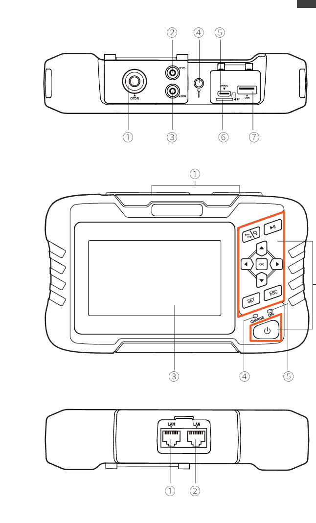
Host
Top
① OTDR port
② VFL port
③ OPM port
④ Flashlight
⑤Type-C
⑥ TF(Mico SD)card
⑦ USB
Main view
① Dust cover
② Function keys
③ 4.3 inch color LCD
④ Charging indicator
⑤ Power on status indicator
Bottom
① RJ45 Sequence test port
② RJ45 Cable line length/cable tracking port
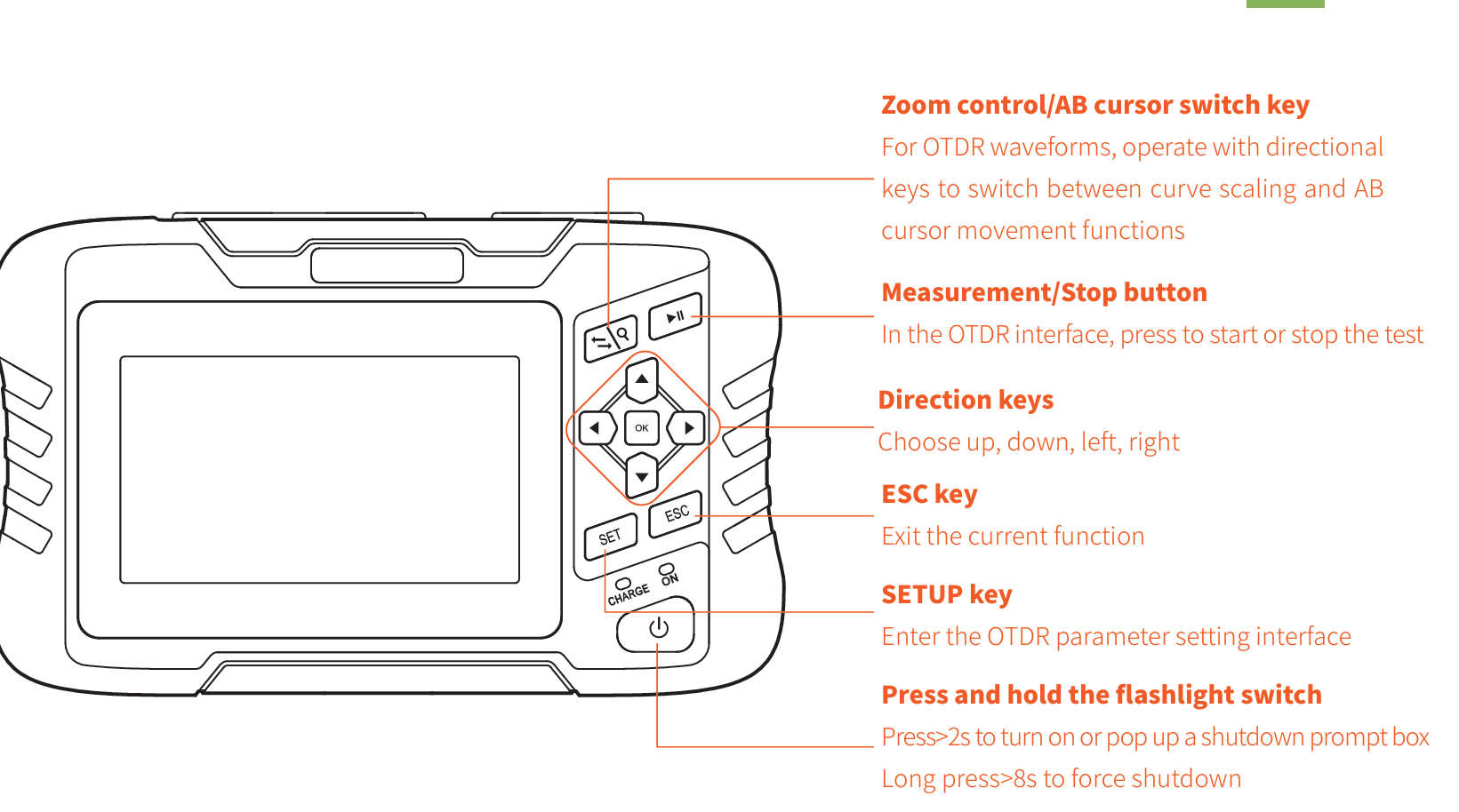
Function buttons
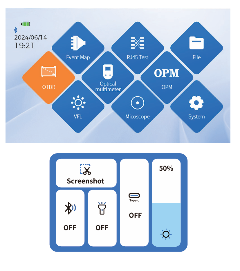
Main interface
After booting up, enter the main menu with a total of 9
functional modules. Press the directional keys to select the
module, then press the "OK" key or directly press the func
tion icon to enter the corresponding functional interface
Press the "Shortcut Menu" to enter the operation interface,
and press different icons to achieve the corresponding
operation functions.
Key operation:Select the function menu up, down, left,
right, and OK to enter the function item.
Screenshot: Capture the current interface, and the image
will be automatically saved inside the instrument. The file
name is the time when the screenshot was generated
 OTDR
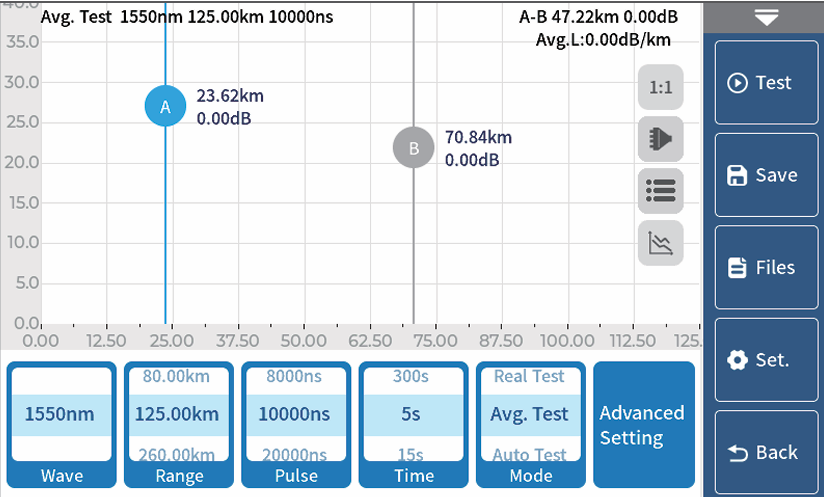
OTDR
Select the testing wavelength, range, pulse width, time, and
mode. Different ranges correspond to different selectable
pulse widths.
Advanced settings: Analysis parameters, qualification
criteria, and other parameter settings;
Quick setup:

Curve operation
Curve scaling and dragging:Touch screen gesture oper
ation
Restore initial curve:Click on the screen 1:1
Move cursor:Drag A or B
Physical button operation:
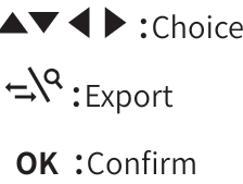
SET :Delete
ESC :Return
:Choice
:Export
OK :Confirm
Gain events :Fiber fusion points of different specifications
Down event :Melting point or bending loss
Reflective event :Connectors, square flange, SC, ST, LC connectors, etc
Fiber end :End of link
10 Event map
This function is completely one click automatic testing,
displaying the length, connector type, breakpoint position
and other information of the measured optical fiber link in
a graphical form, with clear and easy to understand
results.
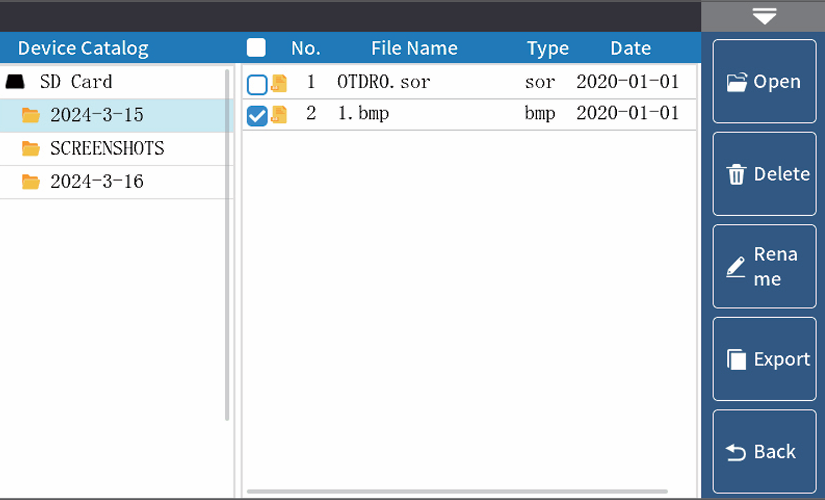
Starting point of the link
Drop event, mostly involving fusion points
Connector, square flange, SC, ST, LC connectors, etc
Fiber optic macro bending, high loss bending point
End of link
Physical button operation:
SET:Pop up options for setting test parameters and
automatic saving
ESC: return
 :Testing and Stopping
 :Cursor switching (move cursor position with left and right buttons), zoom in mode (zoom in with up, down, left and right buttons)
Warning:Do not test wavelengths with light when not online!
Event type: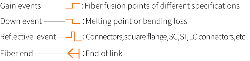
OTDR-Set test parameters
Wave: The wavelength at which light waves are emitted.
Range: Select the corresponding predefined range based on the
actual length of the optical fiber, which must be greater than the
length of the measured optical fiber, usually set to about twice the
length of the measured optical fiber
Pulse : Refers to the time width of the optical pulse signal emitted
during measurement. The larger the pulse width, the stronger the
optical power injected into the fiber, the stronger the backscatter
signal of the fiber, and the farther the OTDR can effectively detect.
However, a large pulse width can cause saturation of the initial reflection signal, resulting in a large blind spot. The selection of pulse width is related to the length of the measuring fiber. The
longer the length, the greater the pulse width, which can only be modified in real-time/average measurement mode.
Mode: The equipment is divided into three modes: automatic testing, average testing, and real-time testing. Automatic testing auto
matically selects testing conditions without the need for manual selection. Average testing and real-time testing require manual
selection of testing conditions.
Time: In the average measurement mode, the longer the detection time, the better the signal-to-noise ratio improvement of the
signal, and the more accurate the test results. Users should choose the measurement time reasonably, and the measurement time is
directly proportional to the measurement dynamics.
Unit: Select the desired unit, with three options available: km, kft, and mi (miles).
Auto save: Whether to automatically save the test file after testing is completed.
Refractive Index: Determined by the inherent characteristics of optical fibers and provided by cable or fiber manufacturers, refrac
tive index is a key parameter for calculating distance and cannot be set arbitrarily. The range of refractive index is 1-2.
Key operation: Press the SET key to enter parameter settings, select parameters up, down, left, right, and OK to confirm the parameters.
OTDR-Threshold/Criterion
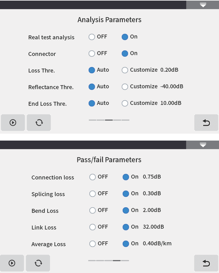
Threshold setting
Event loss threshold: Set the loss threshold for the connection
points, fusion points, or macro bends in the link that can be tested,
between 0.01dB and 9.99dB, with a default of 0.20dB. Events exceed
ing the set threshold will be listed in the event table, while events
below the threshold will be ignored.
Reflection threshold: Set the return loss threshold for the link reflec
tion events that can be tested, between -99.99dB~1.00dB, with a
default of -40.00dB.
End threshold: Set the loss value at the end of the link that can be
tested, between 1dB and 30dB, with a default of 10dB.
Qualification criteria
Set a judgment value for the average loss of connection/fusion/bend
ing/link. If it is less than the judgment value, it is judged as "PASS",
otherwise it is "FAIL".
Connection loss: Reflection event, referring to flange, SC, LC and
other joints;
Welding loss: Non reflective event, often referring to the welding
point;
Bending loss: Non reflective event caused by fiber bending, requiring
simultaneous testing of two wavelengths;
Link loss: The total loss threshold value of the tested link.
Average loss: The loss value per kilometer of the tested link.
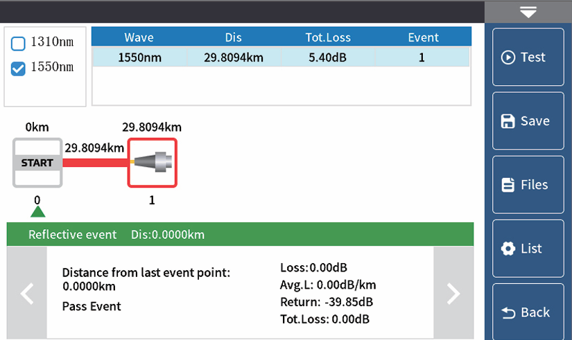
OTDR-Curve
Selecting the correct parameter settings and completing
the test will display test results such as curves and event
lists.
Curve scaling
Touch screen gesture operation enters zoom out and
zoom in mode.
Event List
List: The measurement results are displayed in the form of
a list.
Total length of optical cable: The total length of the
currently tested link
Total loss: The total loss of the currently tested link
Average loss: The loss per kilometer of the currently
tested link
In the event list:
Serial number: The order of the current event
Type: The type of the current event point
Distance: The location of the current event point
Section: The distance between the previous event point
and the current event point
Loss: The loss value at the current event point
Slope: Loss value per kilometer from the starting point to the
current event point
Reflection: Return loss value of the current event point
Total loss: The cumulative loss value from the starting point to
the current event point
OTDR-File save
After the measurement is completed, press 【Save】 to
save the file, enter the file name, and press "Enter" to save
the file. The file is saved in a folder named after the
current date.
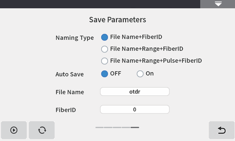
Auto save: Open the file auto save function, and the file
name will be automatically generated according to the
rules.
Naming Type:
File Name+FiberID, with FiberID increasing in sequence;
File Name+Range+FiberID, with FiberID increasing in
sequence;
File Name+Range+Pulse+FiberID, with FiberID increasing in sequence.
File Name: Manually enter the file name.
FiberID: Manually enter the fiber number.
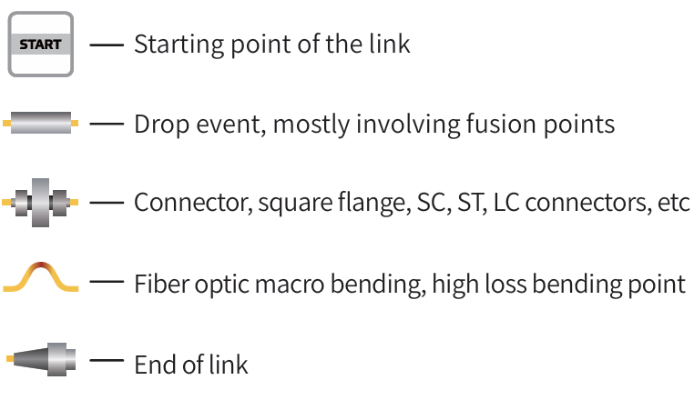
OTDR-File operation
File operation
All test curves are saved in the TF card that comes
standard with the instrument.Press 【 File】 to enter the file
operation interface, where you can open, delete, and
rename files.
【 Open 】 Support for comparing up to 4 curves.
The internal test sor data of the machine TF card can be
exported through a USB flash drive.
Physical button operation:
SET :Delete
ESC :Return
Event map
This function is completely one click automatic testing,
displaying the length, connector type, breakpoint position
and other information of the measured optical fiber link in
a graphical form, with clear and easy to understand
results.
Physical button operation:

Warning:Please do not make online test except online wavelengths!
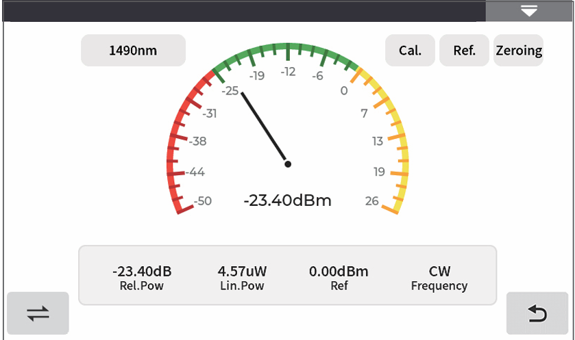
OPM
Used for signal power testing and insertion loss testing of
various devices and optoelectronic components. Can
identify and measure the power of 270Hz/1kHz/2kHz
frequency light.
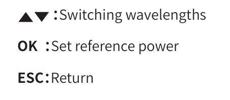
Wavelength: Switching the testing wavelength of the
power meter
Calibration: Enter calibration mode
Reference: Set the current power as the reference power
Zeroing: Reference power set to zero
Physical button operation:
The conversion relations of absolute power, relative power and
linear power are as follows:
PAbs.Pow=10lgPLin.Pow/1mW
PRel.Pow=PAbs.Pow-PRef.Pow
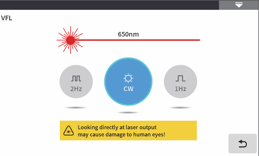
VFL
VFL, abbreviated as VFL, injects visible light (red light) into
the optical fiber and observes the leakage position on the
measured fiber to conveniently and accurately determine
the location of the fiber fault point. Suitable for detecting
near end fault points and high loss sections caused by
micro bends in bare optical fibers, fiber jumpers, and
other optical fibers and cables that can leak red light.
 :Click to turn on/off the red light and output it in
continuous mode
1Hz:Red light flashes at a frequency of 1Hz
2Hz:Red light flashes at a frequency of 2Hz
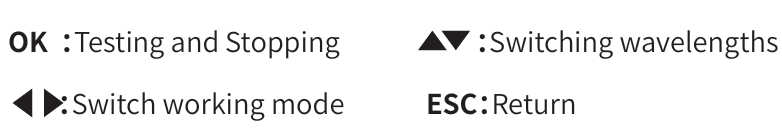
Physical button operation:
OK :Testing and Stopping

ESC:Return
Warning: Avoid looking directly at the laser output port, as the
laser can cause damage to the retina of the human eye!
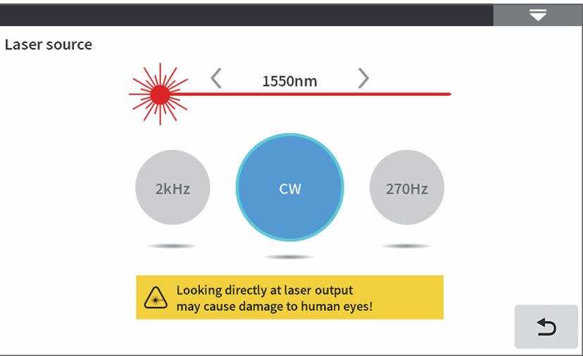
Multimeter-LS
LS, abbreviated as LS, can output laser with the same
wavelength as OTDR function, used for parameter testing
of telecommunications, cable TV, and LAN optical cables;
Insertion loss, isolation, and return loss testing of optical
passive components; Detector wavelength responsivity
testing, etc.
There are five working modes of the light source:CW、
270Hz、330Hz、1kHz and 2kHz。
Open: Turn on the light source
Wavelength: Switching the wavelength of the light source
Mode: Switch light source mode, CW, 270Hz, 330Hz, 1kHz,
and 2kHz
Physical button operation:
Warning :Avoid looking directly at the laser output port, as the
laser can cause damage to the retina of the human eye!
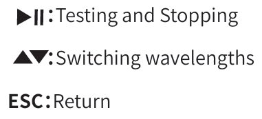
Multimeter-Insertion loss
Used to test the insertion loss value of optical passive
components.
The steps for measuring optical loss are as follows:
1) First, connect the LS and OPM optical interfaces with a
standard jumper, press 【 Enable 】, and after the power
stabilizes, press 【 Reference 】;
2) Use standard jumpers to connect the tested component
to the LS and OPM optical interfaces, press 【 Enable 】, and
the 'Relative Power' will be the insertion loss of the tested
component.
Physical button operation:
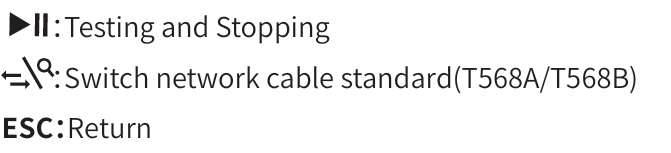
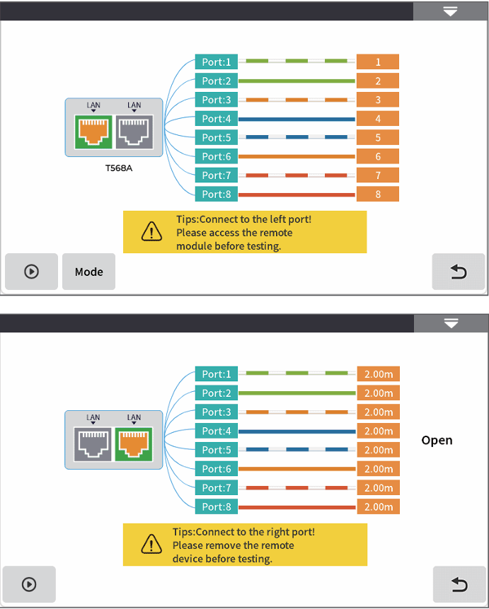
RJ45 Test-RJ45 cable line length /sequence test
Line sequence measurement: During testing, connect the remote end
of the accessory to the other end of the network cable. The testing
modes are direct connection and interleaved connection. Click to start
testing and the order of the network cables will be displayed.
Wire length test: RJ45 wire length is used to test the length and status
(open circuit, short circuit) of Ethernet cables, and supports live testing.
The testing distance range is 1-300m, with a distance deviation of
approximately ± 1.5m.
There are two types of wires for RJ45 connectors: straight through wires
and patch cords.
Network cable standard: T568A/T568B, the color order of the network
cable varies depending on the standard.
Physical button operation:
Warning:The line length/line sequence interface is designated as the instrument interface displayed in yellow.
Please do not connect it incorrectly to cause equipment damage!
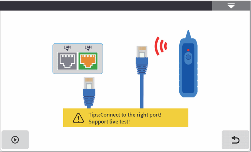
RJ45 Test-RJ45 cable tracking
RJ45 cable tracking test
After the line finding function is activated, touch the
tested cable with the line finder and hear a continuous
"beep beep beep" sound, which is the cable being
searched for.
This equipment is pressure resistant and heat-resistant,
and can be directly used for live wire tracing. Ethernet
switches, routers, and other low-voltage equipment with
a DC voltage less than 60V.
The line finding method of this machine is based on
digital radar, with strong anti-interference ability. The
frequency of the prompt sound varies according to the
distance of the target.
Physical button operation:

Warning:The wire tracing interface is designated as the instru
ment interface displayed in yellow. Please do not
connect it incorrectly to cause equipment damage!
End face detection
End face inspection can achieve real-time monitoring
of the cleanliness of fiber optic joints.
Step 1:Connect the end face detection probe to the
USB-A interface;
Step 2:Click to start;
Step 3:Connect the tested fiber optic cable and check
the cleanliness of the tested end face in real time.
Physical button operation:
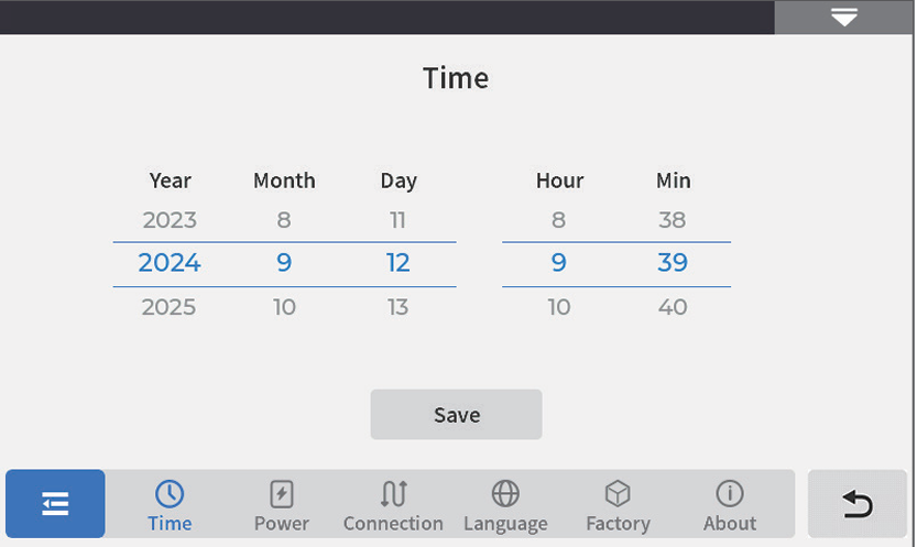
System settings
Time:Set instrument time and date
Power management:Strong light mode, sound, pow
er-saving settings,Backlight brightness(0~100%),
Automatic shutdown (shutdown/5/15/30/60/120 minutes)
Connection: Bluetooth connection, Type-C connection
Language:Display the native language type
Factory mode:Upgrade (local software update), restore
factory settings (restore default parameter values)
About this machine:View local information and alarm
records
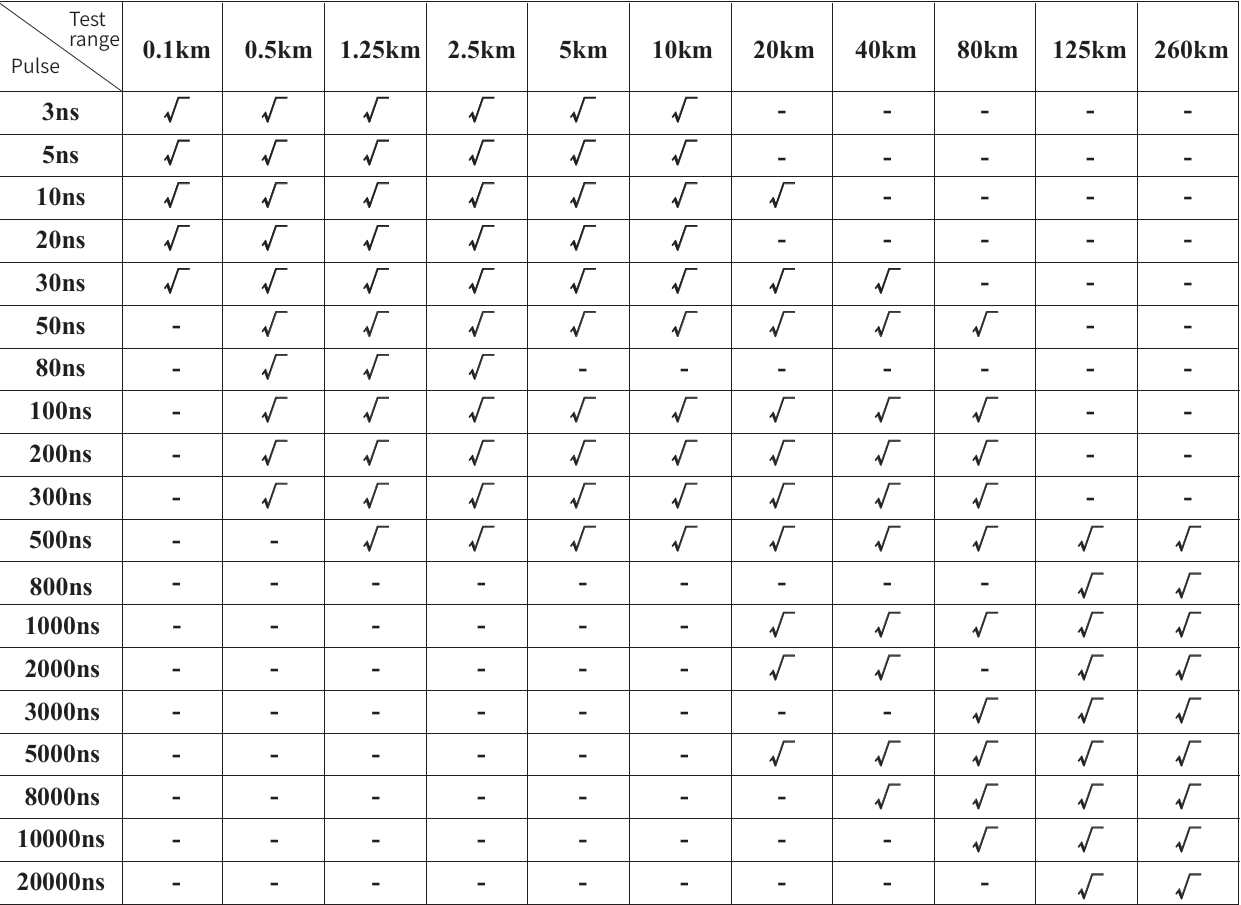
OTDR-Pulse width selection
Under automatic OTDR, when
manually setting the measure
ment range, OTDR will auto
matically select the most
suitable reference pulse width.
In manual averaging mode, the
measurement range and pulse
width can be manually adjust
ed. The list on the right is for
reference only:
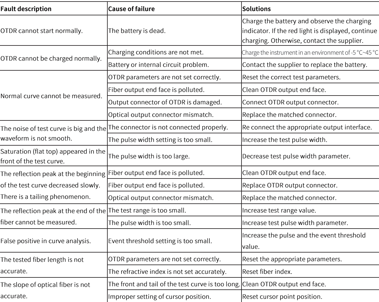
Faults and Solutions
The description in the table
on the right is for reference
only. Please refer to the new
instruction for detailed usage.
In the process of using the
instrument, if you have any
questions, you can contact
the instrument supplier.
Instrument maintenance
Cleaning of connectors
The optical output interface of this series OTDR is replaceable, and the end face must be kept clean during use. When
the instrument fails to test a normal curve or the test results are inaccurate, the first consideration is to clean the connector.
When cleaning, please ensure that both OTDR and visible red light fault location functions are turned off. Unscrew the
output interface and use a dedicated dust-free tissue or cotton swab dampened with alcohol to wipe the connection end
face.
At the same time, please cover the dust cap after using the instrument and keep it dust-proof and clean.
Instrument screen cleaning
The display of this series of optical time domain reflectometer is a 4.3-inch TFT full view color LCD with a capacitive
touch screen. When using, sharp objects should not be used to click on the LCD screen, as it may be damaged. When
cleaning, a soft paper can be used to wipe and clean the LCD screen. Do not use organic solvents to wipe the LCD screen,
otherwise it may cause damage to the LCD screen.


 :Testing and Stopping
 :Cursor switching (move cursor position with left and right buttons), zoom in mode (zoom in with up, down, left and right buttons)


 :Click to turn on/off the red light and output it in


